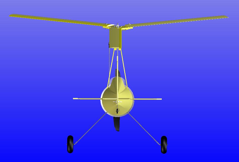
Design parameters:
- Rotor diameter 1000 mm
- 3-blade rotor directly controlled
- Weight around 1 kg
- Rotor disc loading around 12 g/dm2
- Scale like design
- Electrically powered motor
- Controls: Pitch, roll, rudder, throttle
Design steps
Rotor:
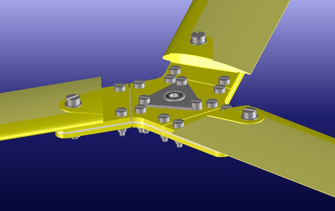
The 3 blade rotor is mounted with ball bearings. The rotor blades are rigged with delta 3 hinges.
Rotor head:
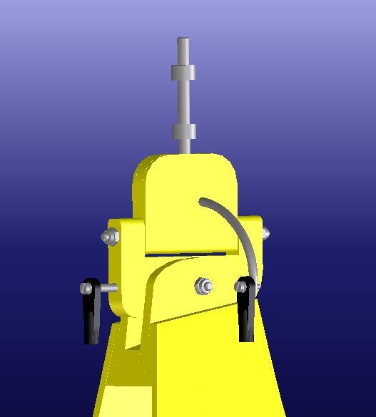
The rotor head is controlled by metal gear servos. Pitch and roll axis are controlled by skewing the whole rotor in the respective direction.
Fuselage:
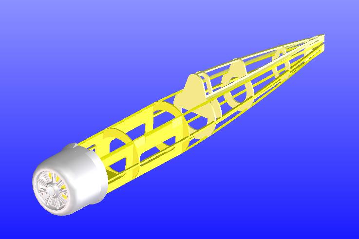
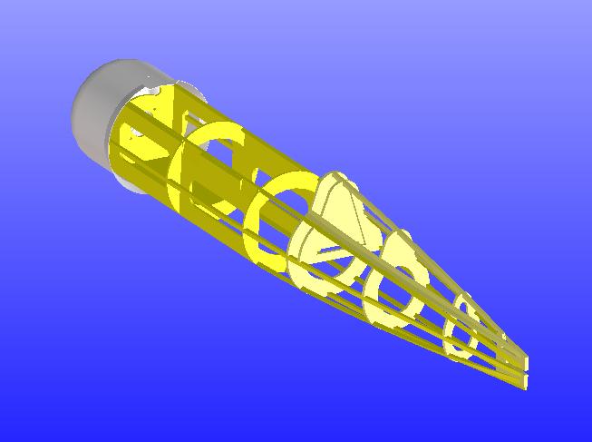
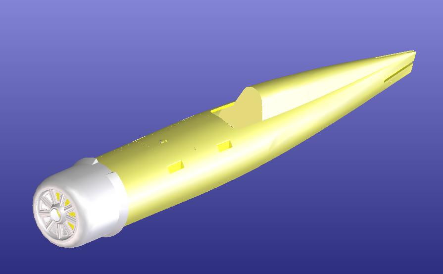
The fuselage is designed around the cowling of the Parkzone Corsair F4U. It is built by formers and strings which are completely planked.
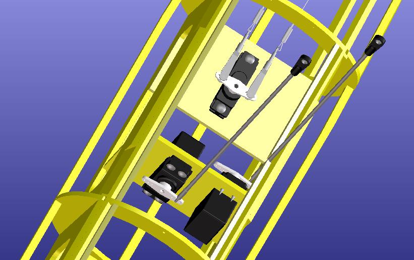
The servo mounting is defined:
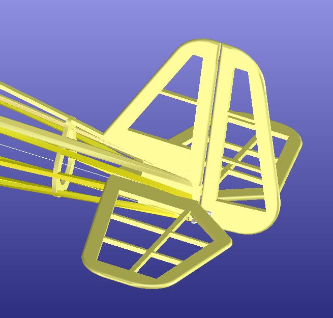
The stabilizers are made in covered lattice construction. The rudder is linked by steel wires.
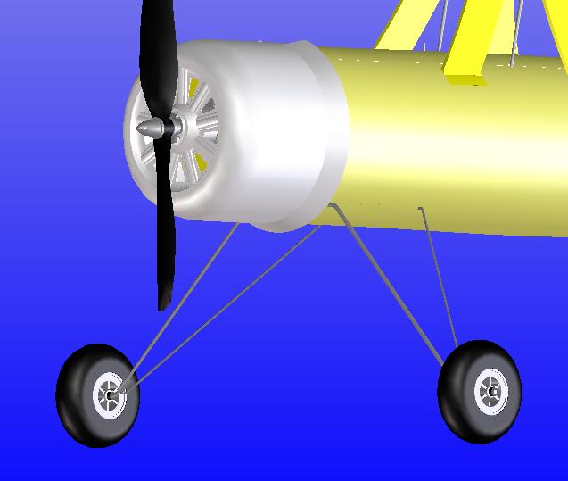
And now the landing gear: The main gear is made of two music wires which are fixed to the fuselage with clamps. Between the rods a fairing could be mounted.
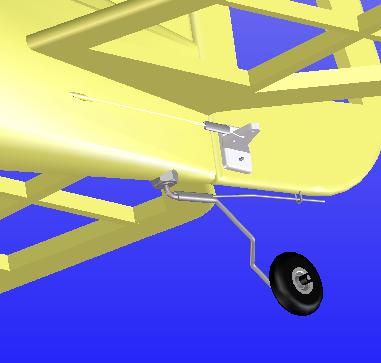
The tail gear is bent from a music wire and is linked to the rudder:
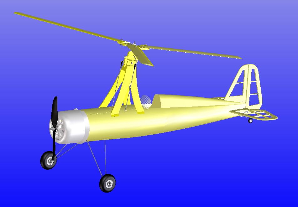
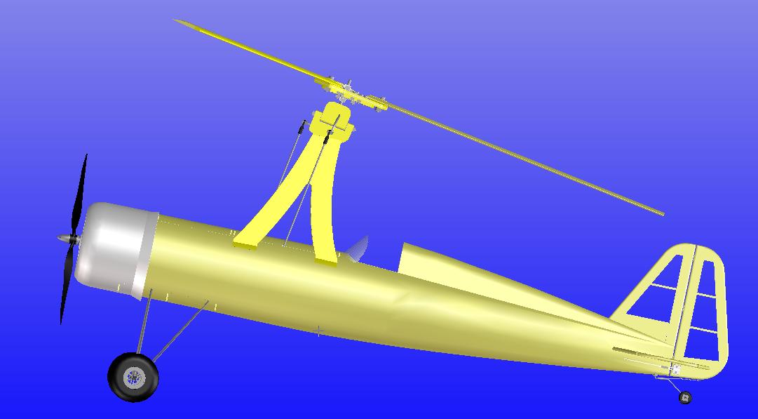
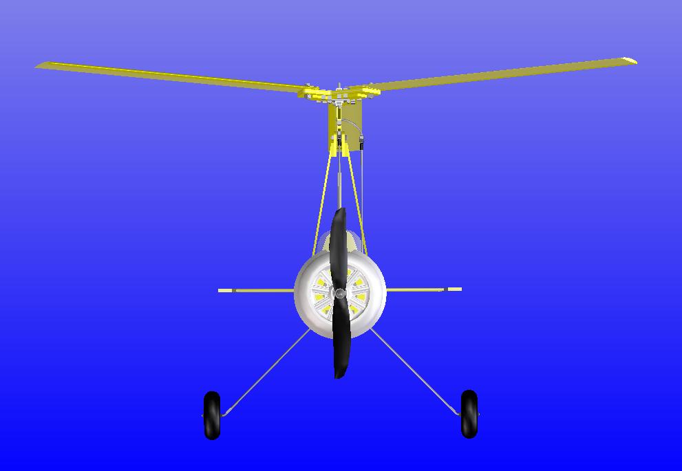
This is how the complete design looks like:
The estimated weight is in a range now in which the rotor disc loading should be around 15 g/dm2.
The 2D drawings are made. Now material acquisition and construction will follow.
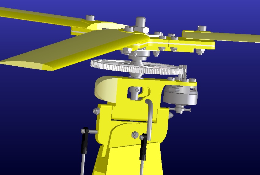
For reducing the take-off distance and simplifying hand launch a rotor pre-rotation gear shall be built. A small brushless motor is driving the rotor via a gear drive. The gear wheel on the rotor shaft has a one-way clutch to allow the rotor to run freely when the motor is switched off (we don't build a helicopter).
The new rotor head will look like this:
Continuation here.


