")
")
After detailed study of the matter I decided to develop my own quadrocopter. These are the requirements:
- 4 to 8 motors
- Electronics based on an up-to-date porcessor platform
- Modern digital sensors if possible
- 4 additional servos
- 4 switching channels
- Status display on the Jeti Box
- GNU cross toolchain
- Extensible with navigation module
This resulted in a first version of the flight controller:


The following main components are used:
- ARM Cortex-M3 processor STM32F101
- 3 axis Accelerometer
- 3 axis Gyroscope
- Pressure sensor
- Temperatur sensor
- Switched voltage regulator for 3.3V and 5V power supplies
- Buzzer
The software is written in C and compiled with the GNU toolchain. I decided to use a small operating system. This allows to program jobs in tasks and let the operating system do the management of the tasks. The target is a modular structure of the software which allows to easily exchange modules with different implementations. The encapsulation of the hardware is also an important issue to allow exchange of hardware components with minimized software adaptation effort.
Subsequently the development environment is shown.

The flight controller is powered from a 3 or 4 cell LiPo battery. In the future also the motors will get the power from it. A small JTAG debugger is connected via the white USB cable for software development support. The black cable is a USB to RS232 converter. Over this cable configuration and maintenance of the flight controller is done from a PC. The colored cable connects a receiver with the flight controller which in turn gets the control signals from the transmitter. With this setup it is possible to develop the software to read the sensors, read the PPM sum signal from the receiver and control the servos and the auxiliary switching channels.

In the mean time a first test platform arose which allows to start controlling the motors.

I have been able to implement and test the basic motor control. The received PPM signals are passed to the motors via a mixer which would allow unregulated control. For safety reasons no propellers are mounted so far (the distance between the motors is slightly too small). The brushless motor controllers of www.mikrokopter.de are used in version 2.
On this platform I also was able to verify the data delivered by the accelerometer and the gyro sensor. Based on this I implemented the attitude control algortihms and did some basic tests. Now a real air frame is required to proceed with testing and parameterization. It's getting a bit mechanical now.
The quadrocopter, which will be named CC-Copter, shall look like this:

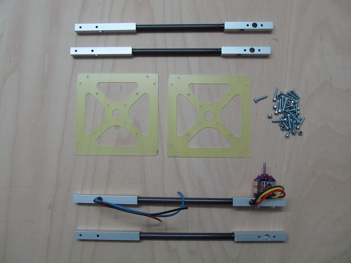
The beams are made of aluminum end pieces and carbon fibre tubes for connection. The central plates are made of glass fibre plates. The distance of the motor axes is 50cm measured diagonally. The target take-off weight should be below 1kg to have enough power in flight.
The beams and the central plates are built and a first motor is mounted to its beam.
The next step is to assemble these parts to get the frame. Then the motors are mounted and the cabeling is done:


And everything looks ready for flight:
")
Now the software must be tested and the PID controllers for controlling the attitude must be adjusted. This will be quite a bunch of work. On this test bench the pitch and roll controllers are tuned.

The adjustment of the PID controllers is taking some more time. But I'm still keeping at it.
There were some problems on integrating the gyro signal to get reliable angular values. Additionally the fusion of the acceleromater data and the gyro data was not working properly. These problems are solved now. So the PID controller parameterization can proceed.
Well, now the settings of the PID controllers of the pitch and roll axis are looking good. For tuning the PID of the yaw axis this harness will be used:

Now everything should be ready to start careful flight attempts.
After fitting the landing gear and balancing pitch and roll axis I made tentative experiments in the cellar. These looked very promising. Therefore I continued outside. The Result looks very impressive. Pitch and roll axis can be controlled pretty good. Just the yaw axis is reacting bad. Anyway some pictures of thje first hops:


My quadrocopter is working pretty well now. It is fairly well controllable, may be a bit sluggish. This can be improved by tuning the PID controller settings.
In the mean time I started to develop the altitude controller. The air pressure sensor is working pretty well already. The controller itself is not ready yet. For stabilizing the signal of the pressure sensor I filter it by software. Additionally I closed the opening of the sensor with compressed rubber foam. The rubber foam is compressed by heat shrink tube. Like this the pressure ripple caused by the propellers is pretty well flattened.

It was quite quiet here for a long time now. In the mean time the navigaton module arose. Beside a micro processor it consists of a magnetic field sensor, a GPS module, an SD card holder and a USB interface. The following pictures show the set up and the mounting on the flight controller:


The next step is the test of the hardware before the development of the navigation software can start.
The hardware test have been completed successfully. The basic software containing operating system, file system on SD card and USB interface are ready. The compass chip is delivering data which are used by the software for computing heading information. The flight controller is delivering roll and pitch attitude information which allow the compass software to compensate tilt. Like this the heading information is correct independent from tilt.
The data of the GPS module can be read and evaluated now. I wrote a handy app which can show the position on Google maps an track the way. The position data are stored on the SD card if it is plugged in. With these log data I'll try to develop an algorithm for holding the positon.
In the mean time I am able to calculate the difference vector to the stored reference position and send it as a correction vector to the flight controller. From this the corrcetion values for the motors must now be caluclated.
Stay tuned ...